Measurement Errors & Electrical Instrument Principles
Classified in Physics
Written on in  English with a size of 12.33 KB
Classification of Measurement Errors
Error is defined as the difference between the actual measured value and the true predetermined value. Errors in measurement are classified into four main categories: systemic, random, gross, and limiting errors.
Systemic Errors
These errors are caused by environmental changes, instrumental faults, and incorrect observations. Systemic errors are further classified into instrumental, observational, and environmental errors.
Instrumental Errors
They occur due to faulty instruments, improper use of apparatus, or instrumental loading effects. Moreover, imprecision in assembly, calibration, or operation is the source of intrinsic errors. These errors are easily detectable. Correcting them involves recalibration and meticulous planning of the measurement process.
Observational Errors
Parallax error occurs due to misalignment between the line of sight and the pointer on a scale. Observational errors are common in analog instruments. Therefore, using digital display apparatus with highly accurate meters helps prevent these errors.
Environmental Errors
External conditions may affect the instruments’ functioning. These circumstances include temperature, dust, humidity, vibrations, and electromagnetic fields. Corrective measures for environmental errors include maintaining a constant environment, using highly resistant apparatus, and applying computed corrections.
Random Errors
Random errors occur due to minute factors that change from one measurement to another. Detecting these errors is difficult as their sources are often unknown. Physicists apply statistical methods to resolve these errors. These methods encompass the calculation of arithmetic mean, range, standard deviation, and variance.
Gross Errors
During experiments, manual errors occur due to faulty reading apparatus or recording results that differ from the actual measurement. These errors are often unavoidable as they are caused by human influence. These errors can be prevented through careful reading, accurate data recording, and taking multiple readings.
Limiting Errors
Factors such as the type of material can impede maximum accuracy. These factors often arise during the manufacturing process. Therefore, manufacturers often guarantee a specific percentage of accuracy. These errors are also known as guarantee errors. Furthermore, the proportion of the error to the predetermined numerical value determines the relative limiting error.
Operating Forces in Analog Instruments
The operating force in analog instruments is the force responsible for moving the pointer to indicate the measured value. Different types of forces act in analog instruments:
- Deflecting Force: Moves the pointer from its zero position.
- Controlling Force: Brings the pointer to rest at the correct position (e.g., provided by springs).
- Damping Force: Prevents oscillations and brings the pointer quickly to the steady position.
PMMC Instrument Working Principle
A PMMC type instrument works on the principle that a current-carrying conductor placed in a magnetic field experiences a force that tends to move it. It operates based on the electromagnetic effect: as the coil carries current and a magnet produces flux, a pointer connected to the coil deflects proportionally to the current. The force in the magnetic field generates the deflecting force. A damping force is also generated, which helps maintain the pointer's stability. Equilibrium is attained by the controlling and deflecting torques, ensuring accuracy.
The interaction of the magnetic field with the permanent magnet produces torque on the conductor (coil). The amount of torque produced is directly proportional to the current passing through the conductor (coil). The coil is attached to a pointer that indicates the reading on the scale. The rotational force (torque) moves the pointer along a scale to display the measured value.
PMMC Instrument Construction
- The Permanent Magnet (M) and a Rectangular Coil (C), which consists of an insulated copper wire wound on a light aluminum frame fitted with a polished steel pivot resting in jewel bearings.
- The magnet is made of Alnico and has soft-iron pole pieces (PP) that are bored out cylindrically.
The rectangular coil (C) is free to move in the air gaps between the soft iron pole pieces and a soft iron cylinder (A) supported by a brass plate.

Construction of PMMC
The instrument consists of:
- M - Permanent magnet
- PP - Soft iron pole pieces
- A - Soft iron cylinder (central core)
- C - Rectangular Coil
- B - Spiral Springs
- D - Pointer
Permanent Magnet (M)
A permanent magnet retains its magnetic property without any inducing field or current. This permanent magnet is used in PMMC instruments to create a stationary magnetic field for the coil to move within. PMMC instruments are the most accurate type for Direct Current (DC) measurements of current and voltage.
Soft Iron Pole Pieces (PP)
These soft iron pole pieces are fixed within the air gaps where the magnet is located. They increase the magnetic flux passing through the coil, making the instrument more sensitive to small currents. They also help direct the magnetic field produced by the coil.
Soft Iron Cylinder (A)
It strengthens the magnetic field and attracts the magnetic field lines, which increases the flux density in the soft iron core. The soft iron cylinder strengthens the magnetic field lines, increasing their number within the core.
Rectangular Coil (C)
This rectangular coil is wound with insulated copper wire on an aluminum frame, acting as the moving element. It helps maintain a uniform field and reduces the reluctance of the magnetic circuit.
Spiral Springs (B)
The spiral springs used in PMMC instruments are for controlling the torque. These springs are made of phosphor bronze and are placed between the two jewel bearings. They also serve as leads for current to flow in and out of the coil.
Pointer (D)
The pointer is linked with the moving coil. The pointer shows the deflection of the coil and the magnitude of its deviation on the scale. Hence, it is easily deflected with the movement of the coil.
Moving Iron Instruments Defined
A moving iron instrument is a device used for measuring current or voltage. This device operates on the principle that an iron piece placed near a magnet is attracted to it. This attractive force is based on the magnetic field strength. This magnetic field is generated by an electromagnet, whose strength depends on the magnitude of the current flowing through it. The basic moving iron instrument diagram is shown below:
Moving Iron Instrument
Construction
The basic construction of the moving iron instrument is explained below.
The device uses the stationary coil as an electromagnet. This electromagnet's magnetic field strength varies directly with the magnitude of the current flowing through it.
Moving Iron Instrument Working Principle
These devices use a stationary copper coil (often wound on an aluminum former) that functions as an electromagnet when current passes through the instrument. The strength of the magnetic field generated by the electromagnet is directly related to the current passing through it.
The iron plates that pass across the coil enhance the stationary coil's inductance (Inductance is a conductor's property that opposes changes in current, generating an EMF when there is variable magnetic flux). An attractive force will be exerted by the electromagnet on the iron sheet.
The sheet that passes through the coil attempts to move along the path of least magnetic reluctance, where reluctance is the magnetic property that opposes the establishment of magnetic flux. Alternatively, the sheet passing via the coil will experience a repulsion force created by the electromagnet. This force enhances the coil's inductance. Thus, reluctance and inductance are inversely related. This describes the operation of a moving iron instrument.
Types of Moving Iron Instruments
There are mainly two types of moving iron instruments:
Attraction type
- Repulsion Type
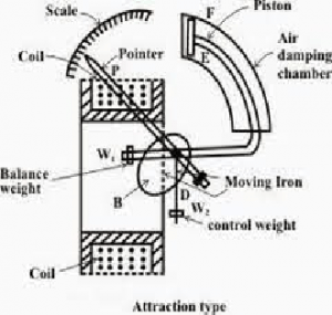
Attraction Type MI Instrument
In this type, the iron plate is attracted towards the stronger magnetic field from the weaker field. Here, the stationary coil in the device is typically flat and has a small opening. The movable element is a flat disc of iron. The flow of current through the stationary coil generates a magnetic field, which exerts an attractive force on the iron disc.
The iron plate will deflect from the region of low magnetic field to high magnetic field, and this deflection is directly related to the magnitude of the current flowing through the coil. In brief, an iron piece is attracted to the coil.
This kind of device uses a spring for torque regulation. The coil’s oscillations are minimized by an aluminum piston attached to the movable coil, which provides damping.
Repulsion Type MI Instrument
This device is constructed with two iron sheets: one static and one movable. These iron plates become magnetized when current flows through the stationary coil, creating a repulsion force between them. Due to this repulsion force, the movable iron sheet moves away from the static plate.
The spring in the device provides controlling torque. Air friction provides the damping torque, which opposes coil movement. These types of moving iron instruments are non-polarized devices, meaning their operation is independent of the current's polarity. Therefore, they can be used for both direct and alternating current measurements.
Attraction vs. Repulsion Type Differences
Attraction-type moving iron instruments possess minimal inductance compared to repulsion types. This makes their voltmeters more precise over extended frequency ranges and allows for enhanced use of shunts with ammeters. Repulsion-type devices are generally more economical, and a more linear scale can be easily achieved with these instruments.
Deflecting Torque Calculation
To derive the expression for the deflecting torque of a moving iron instrument, we consider the energy relations when there is a minimal change in the current supplied to the device. In this view, a minimal deflection ‘dθ’ occurs.
Let ‘Td’ be the deflecting torque. The mechanical work done is Td*dθ. Additionally, there will be a variation in the stored energy, which results in a variation in the inductance value.
Consider the device has 'I' as the initial current, 'L' as inductance, and deflection 'θ'. When the current is augmented by 'dI', the deflection varies by 'dθ' and inductance varies by 'dL'.
By applying the principle of conservation of energy, the deflecting torque (Td) is given as:
Td = ½ I2 (dL/dϴ)
At the final equilibrium position, the controlling torque (Tc) equals the deflecting torque (Td), so:
Kϴ = ½ I2 (dL/dϴ)
Thus, the deflection (ϴ) is: ϴ = ½ (I2/K) (dL/dϴ)
From this, it can be proved that the deflecting torque is proportional to the square of the RMS value of the current. Therefore, the deflecting torque is unidirectional, meaning it operates in a single direction regardless of the current's polarity.