Fundamental Digital Logic Gates: Operations and Equations
Classified in Computers
Written on in  English with a size of 4.24 KB
Fundamental Digital Logic Gates
A logic gate is an electronic device that serves as the physical expression of a Boolean operator in switching applications. Each logic gate comprises a network of switching apparatus designed to satisfy the specific Boolean conditions for its particular operator. Essentially, these are switching circuits integrated onto a chip.
Claude Elwood Shannon conducted experiments using relays or electromagnetic switches to achieve the conditions required for each logic gate. For instance, the Boolean function Y (AND) is implemented using switches placed in series circuit, because if even one switch is in the "open" state, the gate output Y will be 0. Conversely, to implement an OR gate, the switches are configured in a parallel circuit.
AND Gate Operation
The AND logic gate performs the Boolean function of logical product. Its symbol is a dot (·), although it is often omitted. The logical product of variables A and B is indicated as AB, read as "A and B" or simply "A to B." The equation describing the characteristic behavior of the AND gate is:
OR Gate Operation
The OR logic gate performs the logical sum operation.
The equation describing the characteristic behavior of the OR gate is:

NOT Gate Operation
The NOT logic gate performs the Boolean function of inversion or negation on a logical variable. A logical variable A with negation applied is pronounced "not A" or "A denied."
The equation describing the characteristic behavior of the NOT gate is:

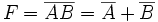
NAND Gate Operation
The NAND logic gate performs the operation of denied logical product. In the figure on the right, symbols can be seen in electronics. The equation describing the characteristic behavior of the NAND gate is:
NOR Gate Operation
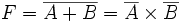
The NOR logic gate performs the logical sum operation denied.
The equation describing the characteristic behavior of the NOR gate is:
Exclusive-OR (XOR) Gate Operation
The Exclusive-OR logic gate (XOR) performs the Boolean function A'B + AB'. Its symbol is a plus sign (+) inscribed in a circle. In the figure on the right, symbols can be seen in electronics.
The equation describing the characteristic behavior of the XOR gate is:
![]() | --
| -- ![]()
Exclusive-NOR (XNOR) Gate Operation
The XNOR logic gate performs the Boolean function AB + A'B'. Its symbol is a dot (·) inscribed in a circle. In the figure on the right, symbols can be seen in electronics. The equation describing the characteristic behavior of the XNOR gate is:
